Custom Power Rail
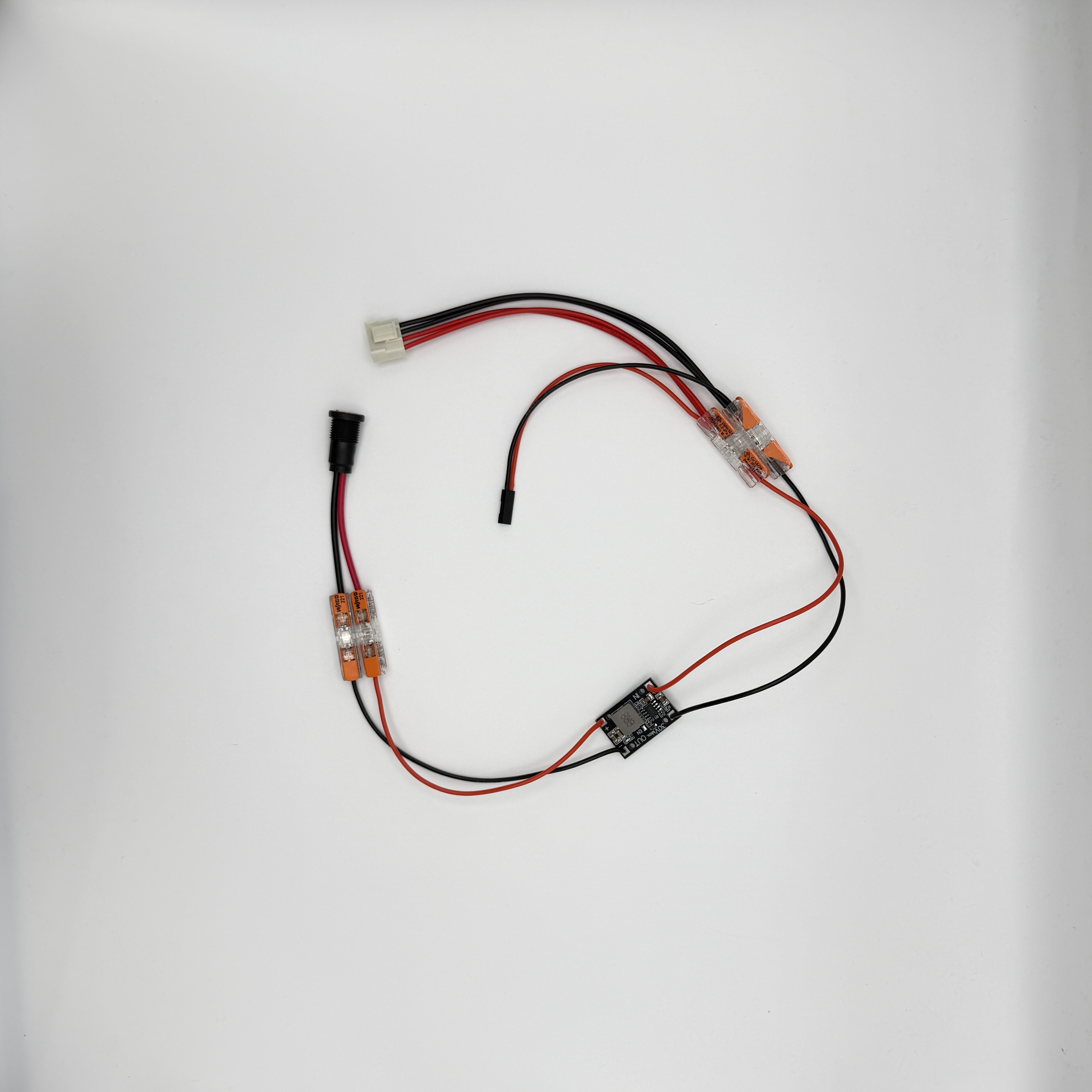
The custom power rail lets one rear 2.1 mm barrel jack power the buck converter, LED matrix, Raspberry Pi, and MatrixPortal. The MatrixPortal remains powered by the Pi over USB.
Check polarity and buck converter output before connecting the Pi, MatrixPortal, or LED matrix. The buck output should be 5 V. A reversed or over-voltage connection can permanently damage the electronics.
Parts
| Part | Purpose |
|---|---|
| 2.1 mm panel-mount barrel jack | Rear power input. |
| DC-DC buck converter | Converts the input supply down to 5 V. |
| 4 Wago connectors | Two for buck input, two for buck output. |
| Trimmed LED matrix power header | Powers the 64x64 matrix. |
| 2-pin Dupont header | Powers the Raspberry Pi from 5 V and GND GPIO pins. |
| Red and black wire | Red for positive, black for ground. |
Wiring Map
| From | Through | To |
|---|---|---|
| Barrel jack positive | Wago connector, or soldered joint | Buck converter IN+ lead |
| Barrel jack ground | Wago connector, or soldered joint | Buck converter IN- lead |
Buck converter OUT+ lead |
Output positive Wago | Matrix power header positive and Pi 5 V Dupont pin |
Buck converter OUT- lead |
Output ground Wago | Matrix power header ground and Pi GND Dupont pin |
The two output Wagos are the rail. Each one takes a buck output lead and then branches to both loads: the LED matrix power header and the 2-pin Dupont header for the Pi.
Build Steps
- Solder four wires to the buck converter:
IN+,IN-,OUT+, andOUT-. - Fit the 2.1 mm panel jack into the rear backpanel and identify its positive and ground terminals.
- Connect the buck
IN+wire to the jack positive terminal using a Wago connector. Solder this joint instead if you do not intend to remove the jack later. - Connect the buck
IN-wire to the jack ground terminal using a Wago connector. Solder this joint instead if you do not intend to remove the jack later. - Power the jack from the intended supply and adjust the buck converter until the output wires measure 5 V.
- Disconnect power before continuing.
- Put the buck
OUT+wire, the matrix power header positive lead, and the Pi Dupont 5 V lead into the same output positive Wago. - Put the buck
OUT-wire, the matrix power header ground lead, and the Pi Dupont GND lead into the same output ground Wago. - Plug the Dupont header onto a Raspberry Pi 5 V pin and a GND pin, checking orientation before applying power.
- Plug the matrix power header into the LED matrix.
Final Checks
Before closing the enclosure:
- Check polarity across the whole rail: jack, buck input, buck output, matrix power header, and Pi Dupont header.
- Use a multimeter to verify 5 V on the rail after the buck converter, measured at the output Wagos.
- After a short powered test, disconnect power and check the buck converter, Wagos, jack, and wiring for any hot spots.
- Check the Raspberry Pi GPIO pins against pinout.xyz before connecting the Dupont header. Make sure it goes to 5 V and GND, not to a signal pin.
Once the rail is checked, apply power through the rear jack. The Pi should boot from the GPIO power pins, the MatrixPortal should power from the Pi over USB, and the LED matrix should power from the trimmed matrix power header.